Millions board metro trains every day. One design flaw has gone unaddressed for decades.
Every time you board a Delhi Metro, an announcement asks you to keep your saree, dupatta, or dhoti away from the closing doors. Most passengers hear it. Many ignore it — not out of carelessness, but because there is a moment of rush, a crowd pressing from behind, and suddenly the doors are closing. What the announcement does not tell you is that even if your garment does get caught, the train's existing safety sensors may not notice at all.
A group of Indian researchers has filed a patent for a mechanism that could change that — not with artificial intelligence or expensive new sensors, but with something far more fundamental: a row of small metal contacts embedded in the rubber strip at the door edge, wired in series, that physically cannot complete a circuit unless both door edges are cleanly aligned.
The door cannot close unless every contact pair aligns. If a single thread of fabric sits between them, the circuit stays open. The door stays open. There is no software to fool, no threshold to slip under.
The Gap That Every Metro System Has
Automatic sliding doors on metro trains have had safety mechanisms for decades. Most rely on one of three approaches: infrared beam sensors that detect when a beam is broken, pressure-sensitive edges that respond when something pushes against the closing door, or motor-current analysis that detects resistance in the drive motor.
Each of these has a detection floor — a minimum size, weight, or resistance below which the obstruction goes unnoticed. A saree pallu, a dupatta, or the end of a dhoti is typically well below that floor. The fabric is too thin to break a beam at an angle. It is too light to register on a pressure edge. And it offers almost no mechanical resistance to a door motor.
The result is a door that appears, to every sensor in the system, to have closed cleanly. The train departs. The passenger, whose garment is now trapped, is pulled.
The Invention: What Actually Changes
The core idea is straightforward. A flexible rubber strip — shaped like a letter I or T in cross-section, the kind already used as a door seal — is modified to carry a row of small, button-cell-sized metal contacts at regular intervals along its length. The same strip is fitted to both door panels, so when the doors come together, the contacts on the left door face the contacts on the right door.
These contacts are wired in series and connected to the door's control unit through a low-voltage 24 V DC circuit. The control unit monitors circuit continuity. It will only allow the door to be considered fully closed when every single contact pair is making contact.
If any piece of fabric, however thin, sits between even one pair of contacts, that pair does not align. The circuit has a gap. The control unit holds the door open or commands a reopening until the obstruction is removed — at which point the system resets automatically, with no intervention required.
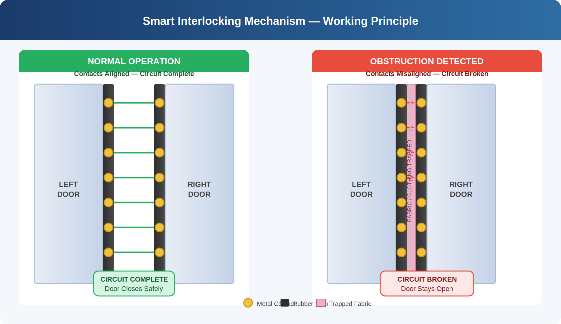
Fig. 1 — Cross-section of the smart interlocking contact strip showing embedded metal contacts in I-shaped rubber profile
Technical Specifications
| Parameter | Value / Description |
|---|---|
| Strip Profile | I-shaped or T-shaped flexible rubber strip |
| Contact Size | ~8 mm diameter (button-cell sized) |
| Contact Spacing | ~40 mm apart along the door edge |
| Strip Dimensions | ~30 mm wide, ~15 mm thick |
| Circuit Voltage | 24 V DC — safe-touch, rail-compatible |
| Circuit Topology | Series — any single broken pair blocks closure |
| Contact Material | Corrosion-resistant metal |
| Strip Material | Wear & weather-resistant elastomer |
| Alert System | Optional audible / visual alarm on repeat events |
| Override | Manual override for emergency / maintenance personnel |
| Applicability | Metro, railway, buses, trams, platform screen doors |
How the System Responds — Step by Step
| 1 | Door begins closing The door panels slide toward each other. The contact-carrying rubber strips on each panel approach alignment. The controller begins monitoring the interlock circuit. |
| 2 | Contacts move toward each other As the panels close, each contact pair on the left strip draws level with its counterpart on the right strip. Circuit continuity is checked throughout the closing cycle. |
| 3 | Decision — is an obstruction present? No obstruction: all pairs align, circuit completes, controller confirms valid closure, door closes normally. Obstruction detected: at least one pair misaligns, circuit stays open. |
| 4 | Response to obstruction The control unit signals the door relay. Closure is inhibited. The door holds open or begins reopening. An optional audible / visual alert may be triggered. |
| 5 | Automatic reset Once the obstruction is removed and all contacts realign, the circuit completes and normal operation resumes immediately — no technician or manual reset required. |
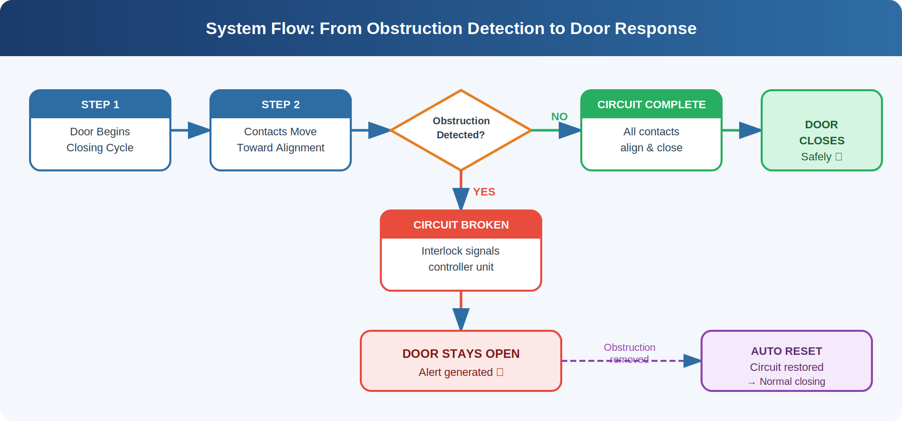
Fig. 2 — System response flowchart: from door closure to obstruction detection and automatic reset
How Does It Compare to Existing Technology?
A patentability search reviewed six international patents and two research papers. The finding was consistent: existing systems have a blind spot for thin, flexible, low-mass objects. Here is the head-to-head comparison:
| Feature | This Invention | IR / Beam | Pressure Edge | Motor Current |
|---|---|---|---|---|
| Detects thin fabric | ✔ | ✘ | ✘ | ~ |
| Low cost | ✔ | ~ | ✔ | ✘ |
| Prevents closure entirely | ✔ | ~ | ~ | ~ |
| Retrofittable to existing doors | ✔ | ✔ | ✔ | ✘ |
| Automatic reset on clearance | ✔ | ✔ | ~ | ~ |
| Reliable in crowded conditions | ✔ | ✘ | ~ | ✔ |
✔ Fully supported · ~ Partial or conditional · ✘ Not supported
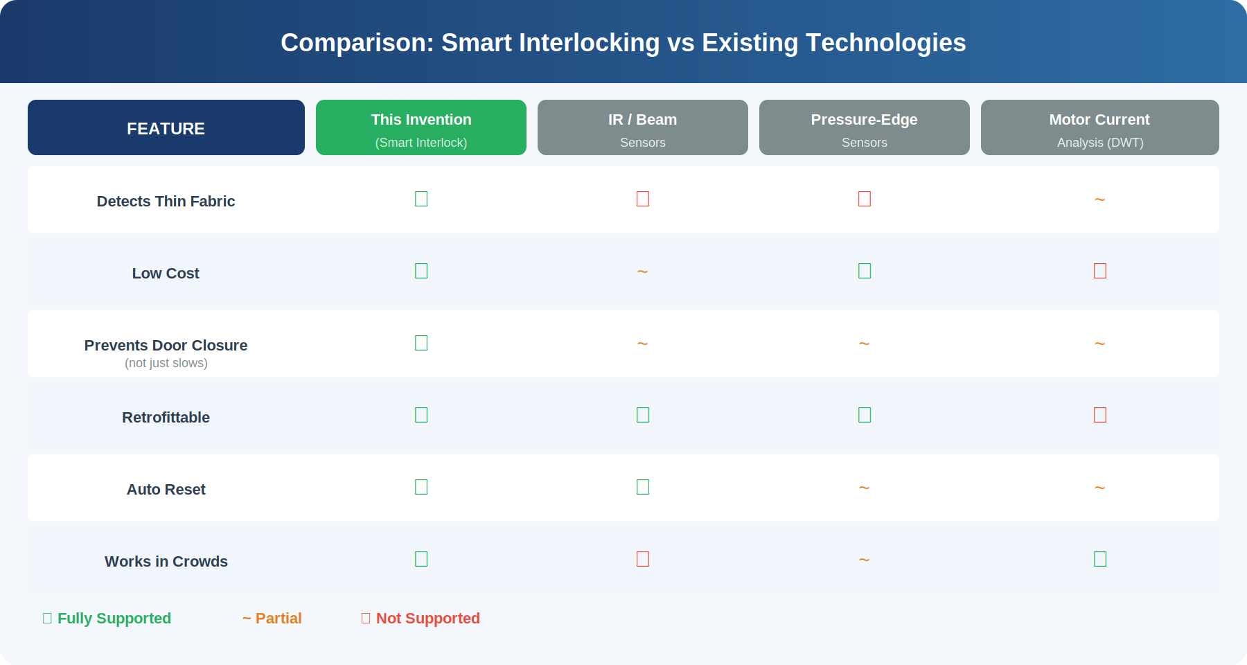
Fig. 3 — Visual comparison of smart interlock versus existing detection technologies
The fundamental difference is what the mechanism verifies. IR sensors verify the absence of a solid object. Pressure edges verify the presence of force. Motor-current systems verify resistance to movement. The smart interlock verifies something more basic: have the two door edges reached true, unobstructed alignment? That is a question neither software nor indirect measurement can answer as reliably as a row of aligned metal contacts.
Key Features at a Glance
| 🔒 | Detects any obstruction, however thin A series circuit with no threshold — either all contacts align or none of them do. A single thread of fabric breaks the chain. |
| ⚡ | 24 V DC — safe and rail-compatible Operates within standard low-voltage ranges already present on rolling stock. No separate power supply needed. |
| 🔄 | Automatic reset — no intervention required When the obstruction is cleared, contacts realign and the circuit restores itself immediately. Door resumes normal operation. |
| 💰 | Cost-effective and retrofittable The rubber strip and contact assembly can be fitted to existing metro coach doors with minimal modification — practical for large fleet upgrades. |
| 🔔 | Optional alert system Repeated obstruction events can trigger audible and visual alarms, notifying station staff or the driver. |
| 🚇 | Broad applicability Metro trains, suburban rail, city buses, trams, airport shuttles, platform screen doors — anywhere automatic sliding doors are used. |
| 🛡️ | Emergency override A manual override accessible to authorised personnel ensures operational flexibility during evacuations and maintenance. |
Patent Filing Status
The patent was officially filed with Intellectual Property India (Controller General of Patents, Designs & Trade Marks) on April 10, 2025.
| Application Number | 202511035168 |
| Reference Number | TEMP/E-1/39052/2025-DEL |
| Filing Authority | Intellectual Property India — Delhi |
| Form Filed | Form 1 (Complete Patent Specification) |
| Filing Date | April 10, 2025 |
| Lead Inventor | Kartikey Kumar |
| Co-Inventors | Dr. R. K. Viral & Dr. Divya Asija |
| Current Status | Filed — Under Examination at IP India |
What the Patent Covers
The specification includes 11 claims. The core claims establish protection for:
- A flexible rubber strip carrying aligned conductive contacts on both door edges, wired in series, where all must complete for closure to proceed.
- The I-shaped or T-shaped strip profile specifically designed for door-edge integration.
- A 24 V DC series interlock circuit connected to the door motor relay or equivalent control unit.
- A controller response that stops, holds, or reverses the door when the circuit is broken.
- An optional audible and visual alert system for persistent or repeated obstruction events.
- A manual override for emergency or maintenance personnel.
- A method claim covering the complete detection-to-response operating cycle, including automatic reset.
The Bigger Picture
India's metro network is one of the fastest-expanding in the world. Delhi, Mumbai, Bengaluru, Hyderabad, Chennai, Kolkata, Pune — new lines are opening almost every year, adding millions of new passengers to systems that were already busy. Every one of those passengers who boards in traditional dress carries the same underlying risk that existing door sensors are not designed to address.
The smart interlocking mechanism is not a complicated proposition. It asks only one question — are both door edges properly aligned? — and refuses to let the door close until the answer is yes. It costs little, requires no ongoing maintenance beyond what a rubber seal already needs, and resets itself without intervention.
The simplest solutions are often the ones that survive deployment. A row of metal contacts in a rubber strip might be exactly what 6 million Delhi Metro passengers are relying on — someday soon.
The inventors are actively exploring industry partnerships and licensing discussions with metro rail operators, door system manufacturers, and rolling stock OEMs. The technology is ready. The problem is real. The door, for once, will wait.
About the Inventors
Kartikey Kumar is the lead inventor and the author of this article. The patent was developed alongside co-inventors Dr. R. K. Viral and Dr. Divya Asija. Contact: kartikeyjaiswal42@gmail.com
Comments
Post a Comment